Language:


In modern digital appliances power consumption and heat generation are more and more important. CMOS technology significantly contributes to the aim to reduce those. CMOS stands for "complementary metal oxide semiconductor" which describes its principle: complementary MOSFETs are used ensuring that only one of them conducts and the other one blocks. Due to that no current flows, only in case of switching.
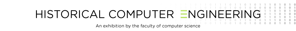
 The most important components are MOSFETs (see figure top row). They controll the connection between S and D. Normally they block. If between G and the terminal marked with an arrow there is a correctly directed voltage applied, they conduct.
Almost everywhere in the entire circuit there is a wire with the defined potential 0 volt. In order to reduce drawing effort the GND symbol is used (see figure bottom right). Of course this symbol can appear more than once. Each applied wire has the potential 0 volt.
Besides the GND-wire there is another wire. Between this one and the GND-wire a supply voltage UDD is applied. Instead of drawing the complete wire its symbol can be used (see figure bottom left).
In the opposite animation the functionality of CMOS technology is explained using the example of an inverter. This component inverts its input. The logical values true and false are represented by the supply voltage and the GND potential respectively.