Language:


The heart of logical Circuits are electronically controllable triggers. In most cases they are realised as metal-oxide-semiconductor field-effect transistors (MOSFET). Compared to conventional transistors MOSFETs have the advantage to only be controlled by voltage, i.e. electrical fields. There is no need for control currents which results in a lower power consumption and a reduced heat generation.
There are some different kinds of MOSFETs. Two levels of differences exist. The first one is the behaviour when no voltage is applied. Either the transistor conducts (self-conducting) or it isolates (self-locking). The self-conducting variant plays a minor role regarding implementation in logical circuits. So only the self-locking ones are explained in this chapter.
The second level of difference concerns the polarity of applied voltages and therefore which kinds of doping to use. There are transistors with n-channel and p-channel. What makes them different will be explained later in this chapter.
 Structure and functionality of transistors with n-channel and p-channel are equal. Just polarities are reversed. So the following explanation only concentrates on n-channel transistors.
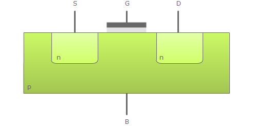
The basis of the transistor is a p-doped silicon crystal. Two n-doped areas are inserted into this base: the source terminal (S) and the drain terminal (D). The purpose of the terminals gate (G) and bulk (B) is to controll the transistor. Seen as a unit the transistor controlls the connection of the gate and drain terminals with the gate and bulk terminals. The gate terminal is not connected directly with the transistor. Between them there is an isolating metal-oxide layer. This ensures that only the voltage between G and B have an impact on the functionality and that no current flows.
The functionality of a MOSFET is explained step by step in the following animation. To avoid misunderstandings please remember that field lines are directed from the higher potential to the lower.
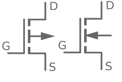 This chapter ends with a hint to the graphical symbol. Self-locking transistors are marked with the dashed line. The gate terminal is the one leading to the solid line, opposite the source and drain terminals. The bulk terminal is marked with an arrow. Sometimes it is connected with the source terminal. For n-channel transistor the arrow points towards the dashed line, for a p-channel transistor in the other direction. So the arrow show the direction in which the electrons flow.
Both kinds of MOSFETs isolate with no voltage being applied. If a n-channel transistor shall be switched to the conducting state, a Voltage between gate and bulk has to be applied (with the higher potential at gate). For a p-channel transistor the voltage has to have the opposite polarity.